

BR MK 1 Full Brake - scratchbuilt
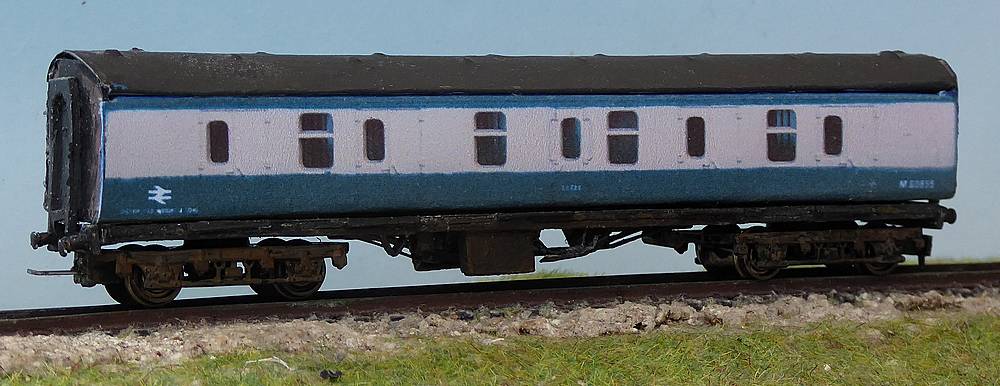
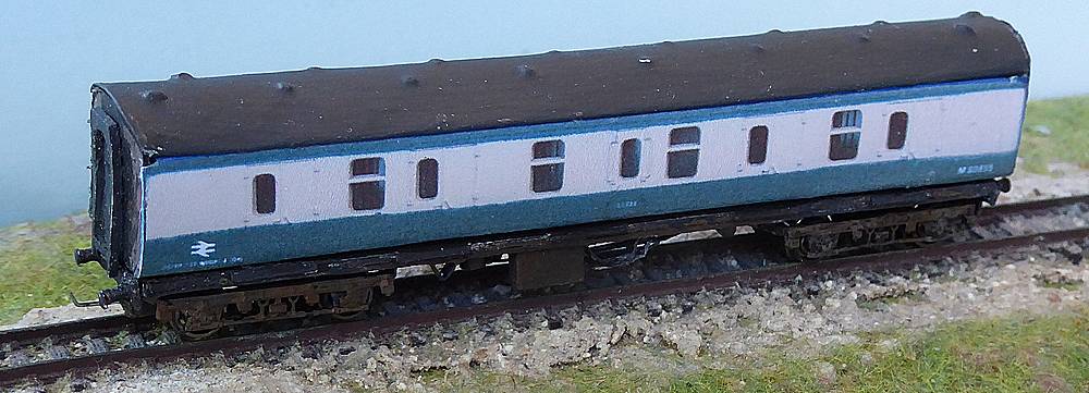
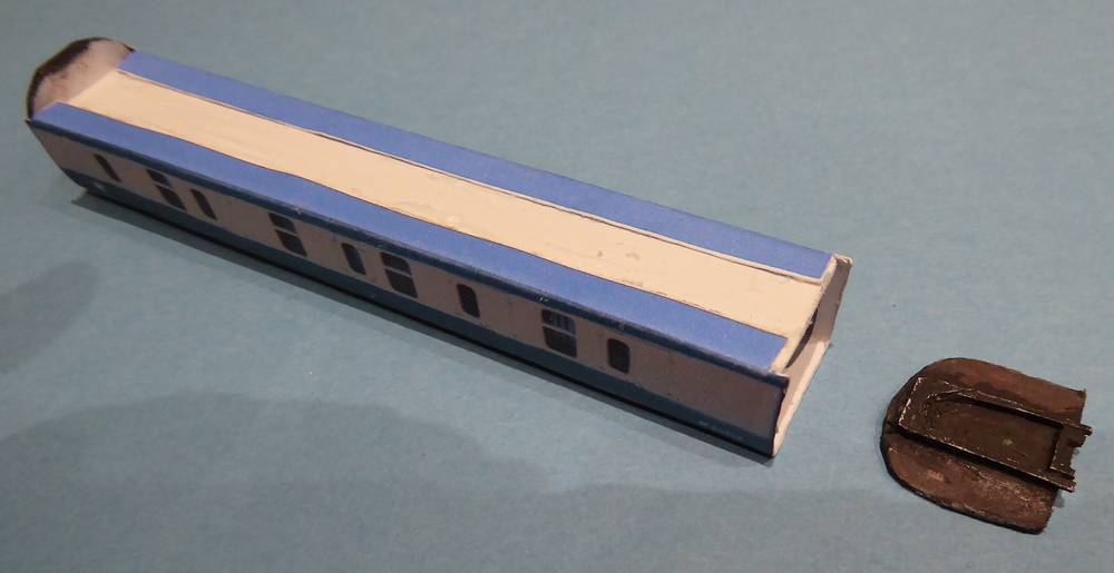
Finished model BR MK 1 Full Brake Parcels Coach
In a previous article, I described how I modified two Graham Farish full brakes in Regional Railways livery to a standard blue/grey livery using paper overlays and how I made a scratch-built chassis for one of them.I wanted to try to make another coach completely scratch-built, mainly from card, using those ideas. I would need to work out how to make the coach shape, how to make the ends with corridor connections and how to make a coach roof. It was not easy and required quite a lot of tinkering until I was happy with the final system.
Chassis
The bogies are MK 1 Graham Farish bogies from Peters Spares and are fitted with Graham Farish coach wheels. The couplings fitted are my own magnetic couplings.
My method for the manufacture of N gauge buffers beams and buffers for coaches is described in the article Buffer Beams and Buffers.
Roof
The base of the roof is of 1 mm foamboard or card with an upright support glued at right-angles down the centre. The roof surface is 90 gsm paper which when fitted will be strengthened with laters of paint and varnish.
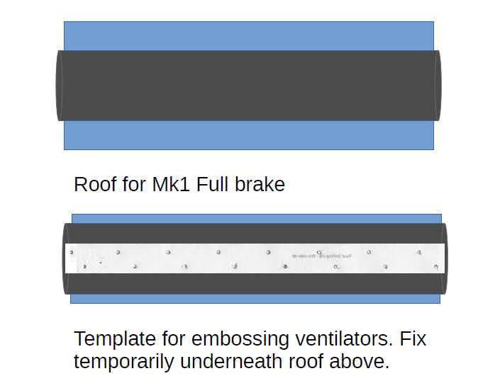
Illustration of roof drawing for printing on copy paper
I discovered that I could make a reasonable impression of a ventilator by embossing the paper with a screw. It made a hole and pushed the card out to form a pimple. It did make a hole in the pimple but this would later be filled with paint.
The curve of the roof was achieved by bending it over and gluing it to the base. It was not easy and I found it better to bend over tabs which I could then glue underneath the base. Keeping the PVA glue away from the edge of the base was found to be important as it could distort the paper. Hence the tabs are generous in width.
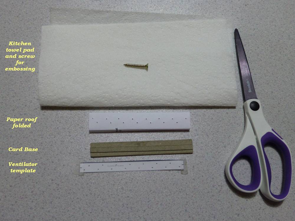
The diagram below shows the technique. It was for another parcels vehicle but the principle is the same. The base used for the model in this article was different to that shown in the photo. The folded paper roof is turned upside down and the template temporarliy fixed to the base ensuring the centres are aligned correctly. This is put onto the folded paper towel and the screw or other pointed object used to make the impressions.
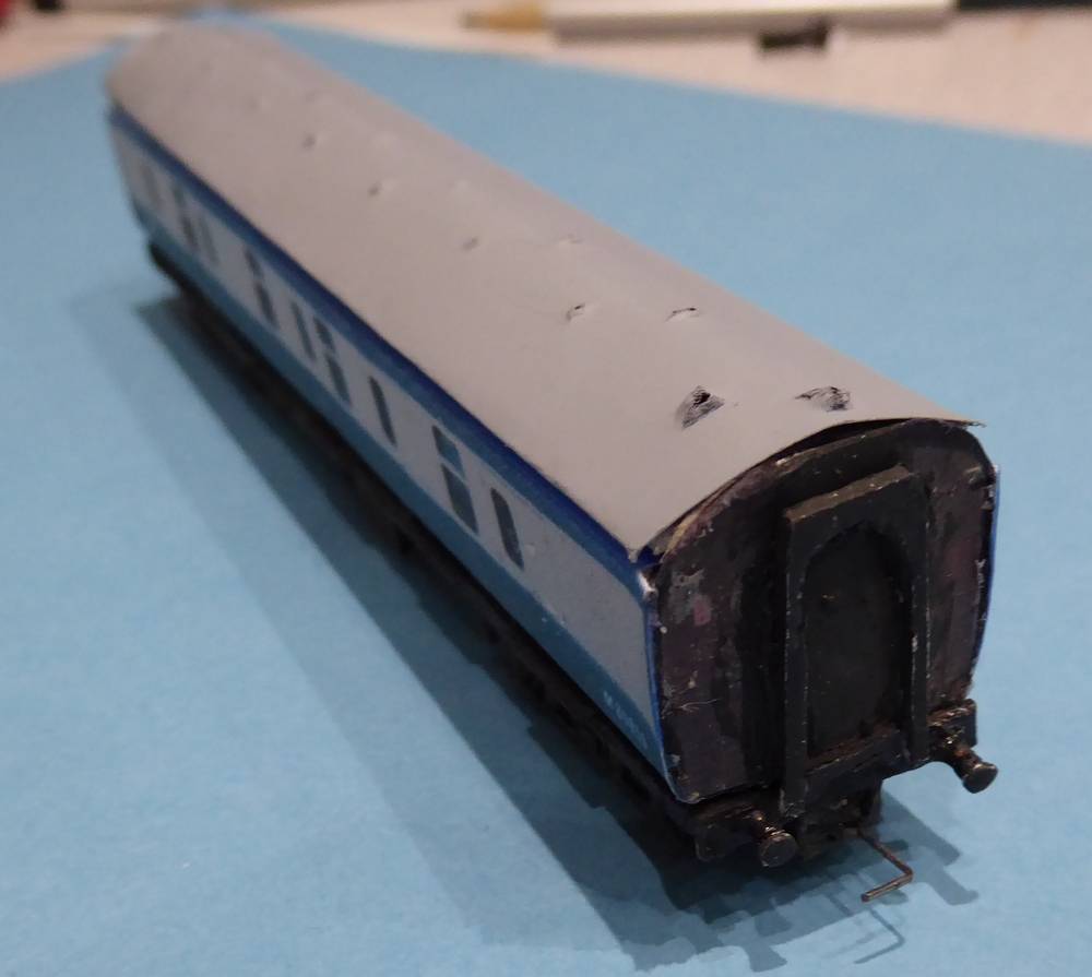
The embossed coach roof after spraying with grey primer and temporarily fitted in place on the coach body. The holes in the "ventilators" will be filled in with paint in the subsequent brush painting.
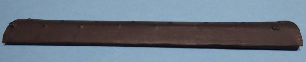
The final roof after painting with Revell Anthracite Grey and then a coat of matt varnish.
Ends
The ends define the shape of the coach including the tumblehome in the lower half of the sides. The end is not flat but bowed with a corridor connection at the centre. The sides are built from copies of two images:-
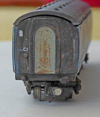
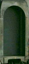
- The end - I used a photo taken of the end of one of my Graham Farish full brakes. I now would prefer to work with one of the images found on the internet taken of a Mk 1 coach straight on.
- The corridor connection taken from an internet image of the prototype
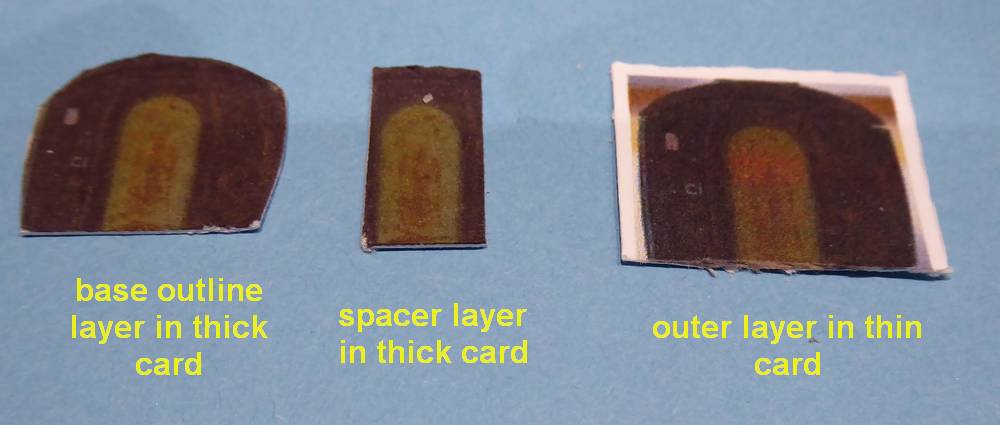
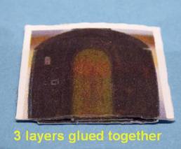
The drawing provides multiple copies of the two images which I printed out on two thicknesses of card - 160 gsm and 300 gsm.
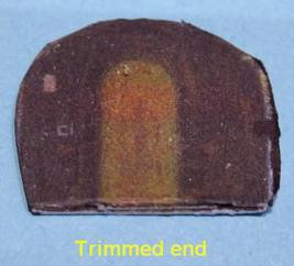
The thicker card provided the overall base cut round the outline; note that the buffer beam has to be cut off the image. On this was glued a central spacer cut from the thicker card but just the central 10 mm. The full outline with a little spare around top and sides was cut from the thinner card to give the outer skin which when glued over the spacer gave the bow section. This layer is then trimmed back to the outline of the first thick card layer,
Body
This uses the same photographed side as used as a paper overlay in my Graham Farish coach conversion. In the drawing, the two sides are either side of a floor base and at the top of the sides are foldover flaps. I did a few trials with the body and found it better to make the whole in one piece with a fold at the top and bottom of the sides to maintain rigidity. The drawing is printed out on 160 gsm card and the surface sprayed with an inkjet colour preservative (Ghiant Inkjet Fix Matte).
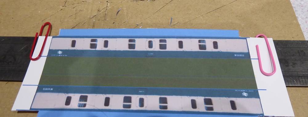
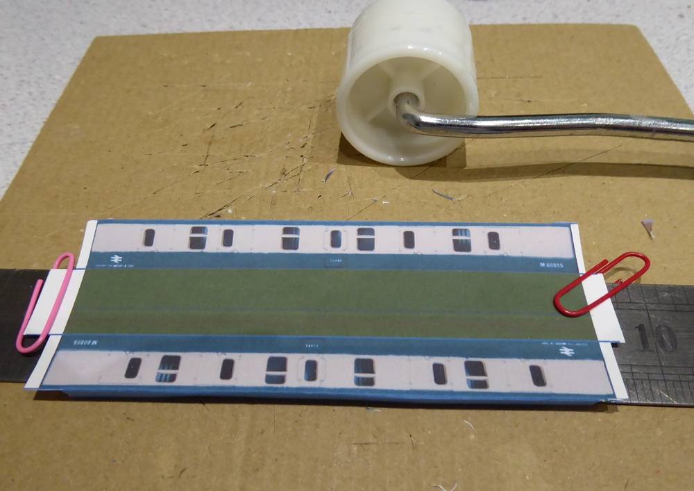
The horizontal cuts were made but enough spare card was left at the ends so the marks for the fold lines could be seen. I used a steel ruler to help with folds as shown above. Paper clips held the card in position on the ruler. The tabs were first bent over. I used a small wallpaper roller to make a sharp edge but any hard object could be used.
THe folds at the bottom of the sides are made next in the same way.
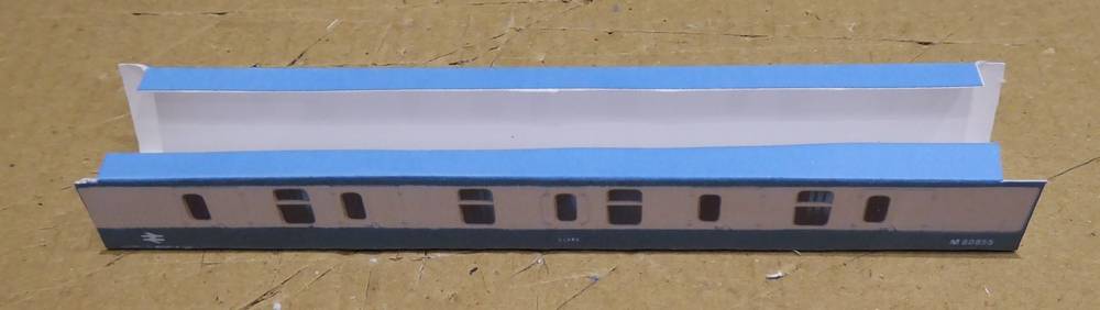
The workpiece is then flattened so that the vertical cuts can be made and then refolded as shown.
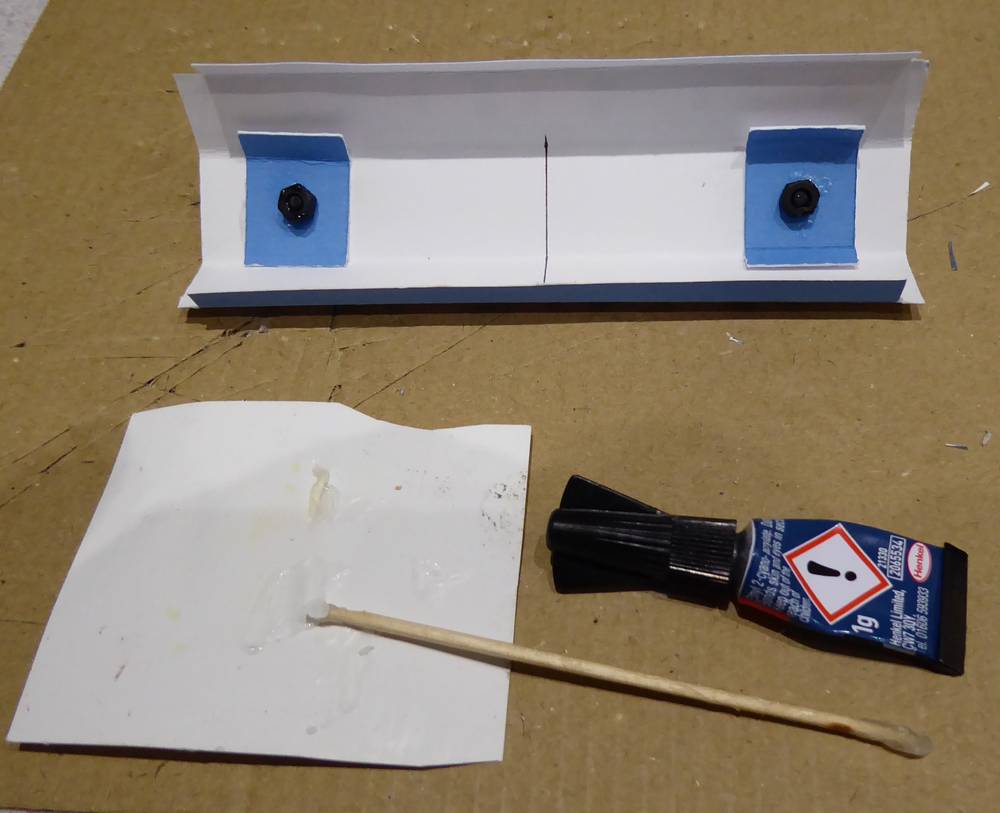
The base is then marked for the bogie pivot points and 3 mm holes made to allow a M3 nylon screw through. Two stretchers are made (as shown on drawing) and thes also are folded up and have 3 mm holes in them. They were glued with PVA glue to the base with the holes lining up. When the glue is set, M3 screws were put through and M3 nuts tightened down on them. These nuts are held in position with superglue spots around the edge of the nut. Care is needed to ensure that none gets on the thread. Once the superglue has set the screws can be removed.
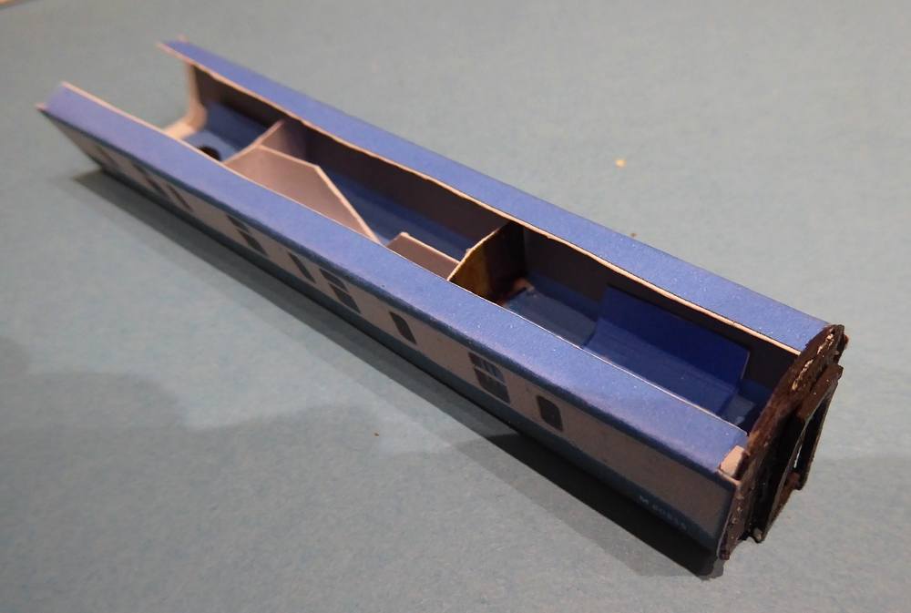
This shows the internal strengthening structure I used. Two partitions are cut from the end profile used for the ends but cut off at the top to allow for the top to be fitted. Triangular supports keep them in place. I found it important not to glue the sides to the partitions as PVA glue here causes local distortion of the sides. One of the ends is glued in. The other is left off at this stage to allow the top to be fitted.
The top was 1 mm foamboard 117 x 19 mm, glued to the end and partitions. Then the tabs are glued to the top making sure that PVA glue does not get near the fold. The other end is then glued in.
The roof has to tried and adjusted to fit into the space between the ends.
Chassis
The chassis starts with 3 layers of card, one thick and two thin. The lowest layer is 2 mm wider than the others and is used to form the steps under the doors.
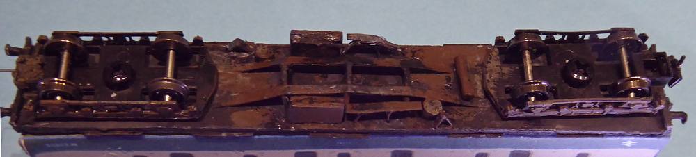
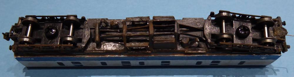
The underframe needs to look realistic when viewed from the side, so we can use card strips side-on and not worry about the width. The only way you are going to get a good view of the real coach underframe is of you are run over by a train and then the width of the truss members may not be your biggest concern. The underframe will also be in the shade so it doed not have to be a perfect representation of reality. The point is illustrated above by the V-hanger which is narrow end-on but is a card strip bent and glued in place by tabs with PVA.
Most of the structure is made from thin card strip; the dynamo is cut from a wooden cocktail stick and the vacuum cylinders are from black Milliput filler. This is surplus filler from other applications which was rolled into a long cylinder and kept for applications such as this. A small section is cut off and fixed in position with superglue. The chassis as shown above is slightly bowed but this will straighten out when it is fixed to the body.
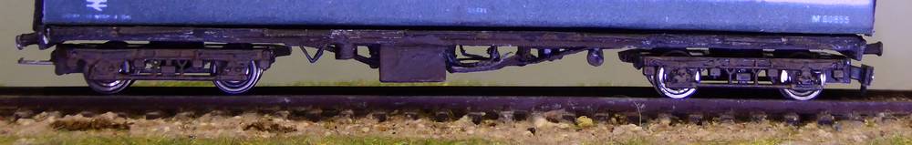
The bogies and chassis were painted with matt black enamel, followed by two washes of a brown earth-like acrylic colour to give it a rusty weathered appearance.

My method for the manufacture of N gauge buffers beams and buffers for coaches is described in the article Buffer Beams and Buffer.
Conclusions
I guess I realised soon after starting to try to scratch-build models in N gauge that my printer coupled to a computer was likely to be my best friend. The ability to print out in colour with fine detail directly onto card, paper or acetate sheet would overcome many of my difficulties in trying to work in such a small scale. The ability to print out coach sides directly would save the hassle of painting and putting on decals and lining. I think this article shows that the idea has merit, although the execution needs further development and more skill on my part.
It was also clear that I would never be able to produce models in such detail as is now available commercially, but life is always a compromise. Rather than look at the detail on N gauge models blown up by photography to look like O gauge models, I prefer to look at photographs of trains on the internet and aim to get something like it looks at a distance, rather like you would actually see on a model layout. Look at the locomotive, coach and wagon and pick the things which hit the eye and should be got right and that which does not matter. Modern coaching stock with tinted windows is mainly flat and you cannot see in the windows. If you want your coaches to be illuminated, then you need clear windows but if you only run trains in daylight then printing them as dark areas onto gloss photocard should work well. Here a parcels coach with small, often dirty, windows really does not need glazing. Similarly, the chassis underframe again very often in shadow only needs to look right when viewed side on.
I was pleased at how the steps on the solebar worked out. It is just an extra layer on the chassis base.
References
Sources of Information and Inspiration:
- Parcels, Mail and NPCCS. Parcels stock from the EMGauge 70s group.
- Paul Bartlett's photographs of parcels stock
Article dated: 11/06/2022